How Can We Help?
Re-Projecting DTM Data
DTM PROJECTION & DATUM
DTM data is a digital representation of the terrain of the Earth. As the world is round (pretty much), the pixel dimensions in x any y are most accurately measured in decimal degrees (spherical coordinate systems). For high resolution DTMs, these pixel dimensions can be really small (0.00001° latitude ≈ 1.11m).
Most software applications (including UE4) work in measurements based on linear coordinates (centimetres/metres x, y, z from an origin point at 0,0,0), and don’t understand spherical coordinates. As a result, when UE4 tries to import DTM data with measurements in degrees (°) lat/lon, it just treats the pixel dimensions as if they were cm/m, and creates a really small landscape.
To make the maths much more straightforward, map makers make the assumption that for a small area, the world is actually flat. They use mathematical models (called Projections) to remove the affect of the curvature of the Earth from geographical data, which make it possible for applications like UE4 to understand the data. Re-projecting DTM data is the process of changing it from one projection to another. (“Datum” is just another word for origin.)
THIS ARTICLE
This article’s all about how to ‘re-project’ data in a round-Earth (spherical) coordinate reference system (“CRS“) to a planar (flat-Earth) CRS. It begins with loading your data into QGIS, so we’re assuming you’ve already got the data you need for your area of interest and have installed QGIS.
If you have other GIS software you prefer (Global Mapper/ArcGIS Pro etc.), you can still follow the same broad steps to prepare your DTM source data for Unreal Engine.
If you haven’t yet got any source data yet, you can download the samples used in this guide.
Step 1
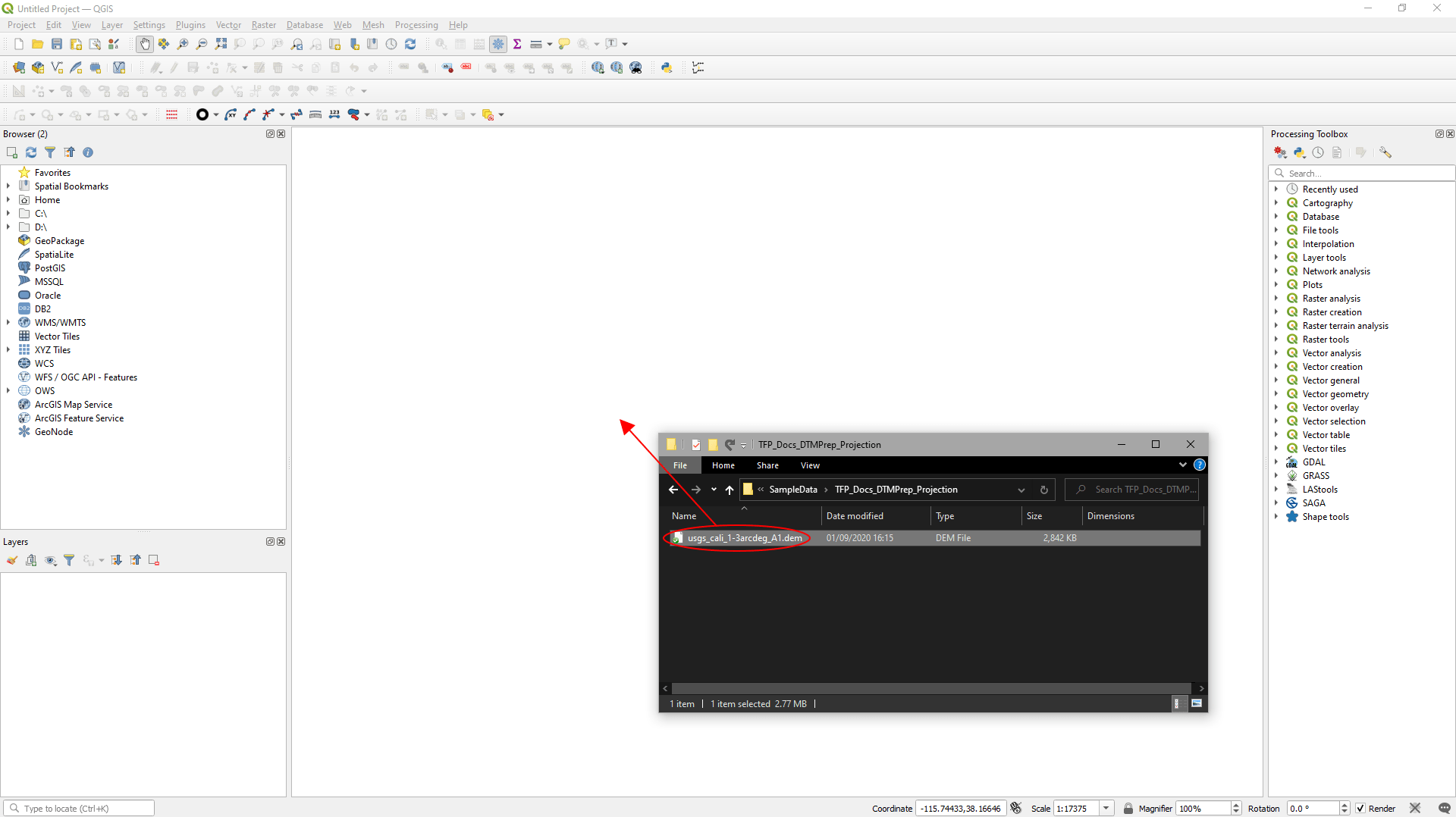
Load the data into QGIS:
- Select the DTM file in File Explorer and drag it into the project window in QGIS.
A new QGIS project will have a default coordinate reference system already assigned. This is the CRS that the data you load will be displayed in. When you load data that’s stored in a different CRS, QGIS may try to transform it to the project’s CRS.
We don’t want it to do this – instead we want QGIS to display our DTM data in the CRS it’s already stored in:
- In the ‘Select Transformation…’ window that appears, click ‘Cancel’.
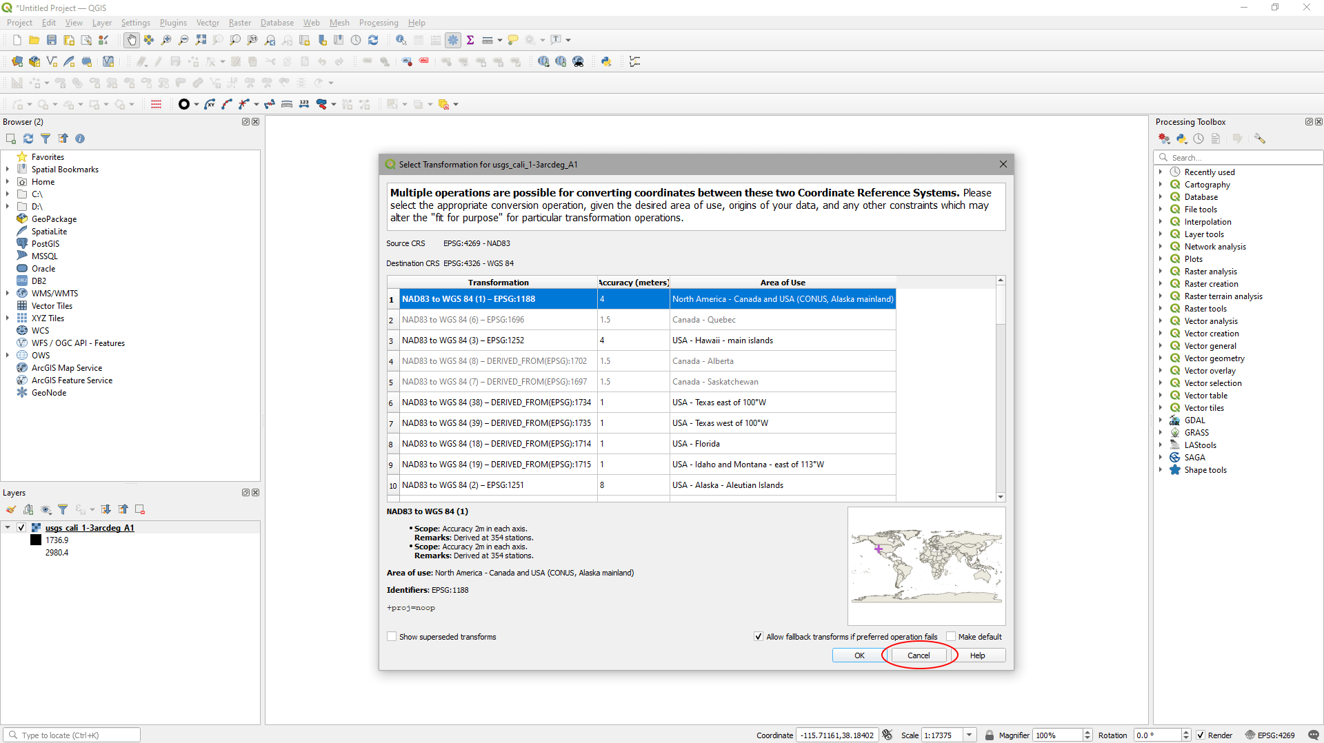
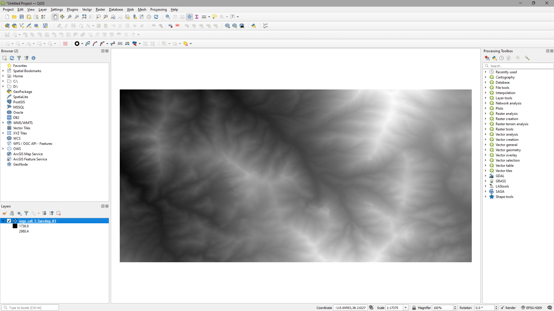
QGIS now will adopt the CRS of the file you’ve loaded.
It’ll look something like this:
Step 2
Check the current projection of the DTM data:
UE4 (/TerraForm) needs data in a Cartesian (planar) coordinate reference system, where the pixel units are linear (centimetres/metres/feet/inches etc.). The first thing we need to do is to check the units used by our data, which tell us if it’s in a round-Earth (degrees), or planar coordinate reference system (e.g. metres).
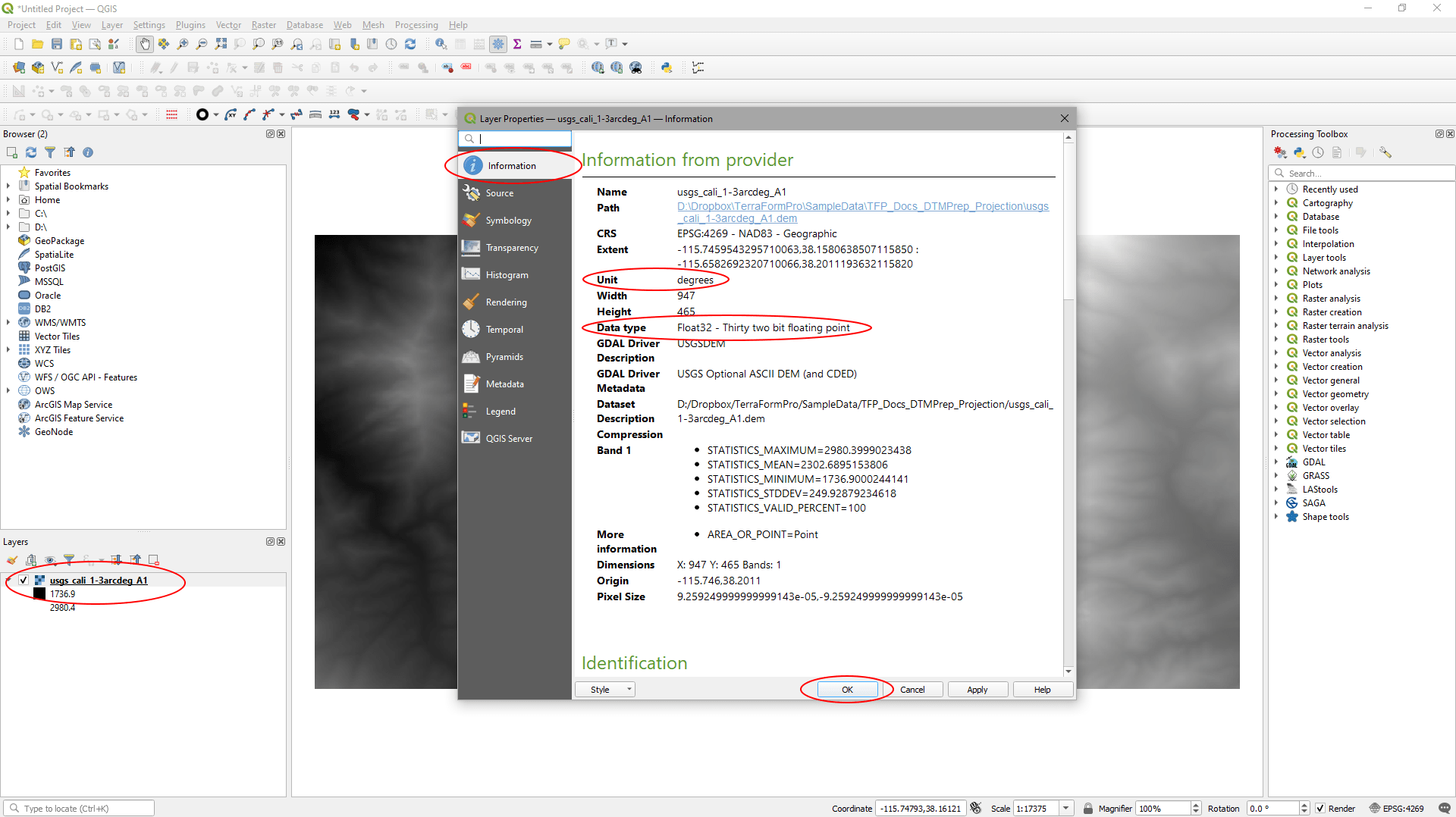
- Double click the DTM file in the ‘Layers’ panel to pull up the ‘Layer Properties’.
- On the ‘Information’ tab, it says the ‘Units’ are ‘degrees’, which means it’s in a round-Earth CRS – we will need to change that.
- It also tells us the data type is ‘Float32’. This is what we want, so we don’t need to change it for this data.
- Click ‘OK’ to close the window.
Step 3
Set the project’s coordinate reference system:
We want to set our CRS to be a Cartesian planar projection. We’ll use UTM (because it’s accurate and available worldwide) and we’ll set the datum (origin) of the CRS to be WGS84. The UTM coordinate reference system is broken up into zones, so we need to find the correct UTM zone for our data. Our data is in Nevada, US. A quick Google search for ‘UTM Zone Nevada’ gives the result: ‘UTM Zone 11N’.
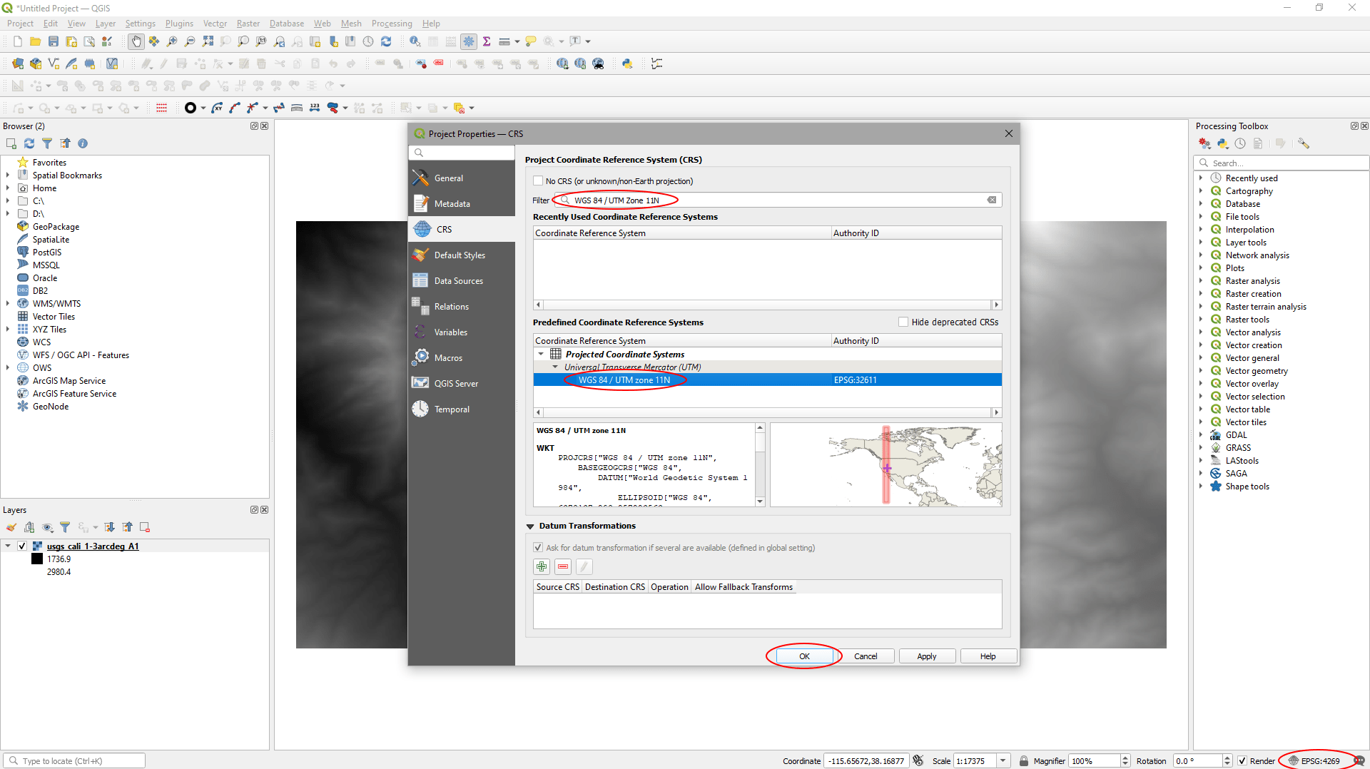
- The project’s current CRS is shown in the bottom right corner of the screen. In our example it’s EPSG: 4269. Click this to change it.
- Typing ‘WGS 84 / UTM zone 11N’ into the filter gives result we want in the ‘Predefined Coordinate Reference System’ section.
- Select this and click ‘OK’.
In QGIS there are multiple mathematical formulae to transform data from one coordinate reference system to another. We want to select a transformation with a low error value (‘Accuracy (meters)’) and with an appropriate ‘Area of Use’. Given our data’s in Nevada and is north of 38N Latitude, we’ll go for option 3.
- In the ‘Select Transformation…’ window, select option ‘3’.
- Click ‘OK’.

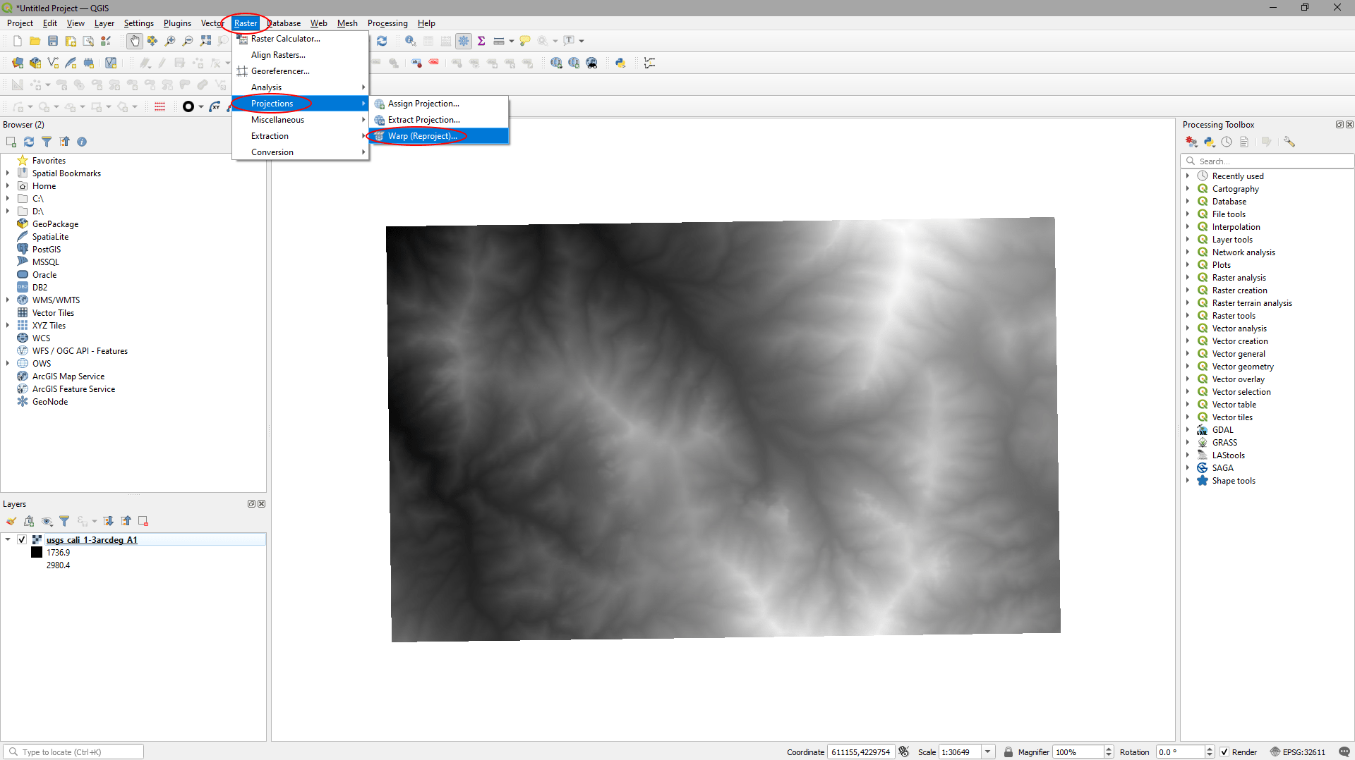
The DTM appears skewed because we’re now displaying data stored in round-Earth coordinates in a flat-Earth coordinate reference system.

Step 4
Re-project the DTM data:
Although our DTM’s now displayed in a UTM projection, the source data is still in the original round-Earth coordinate reference system. We need to re-project it.
- Click ‘Raster’ > ‘Projection’ > ‘Warp (Re-project)…’
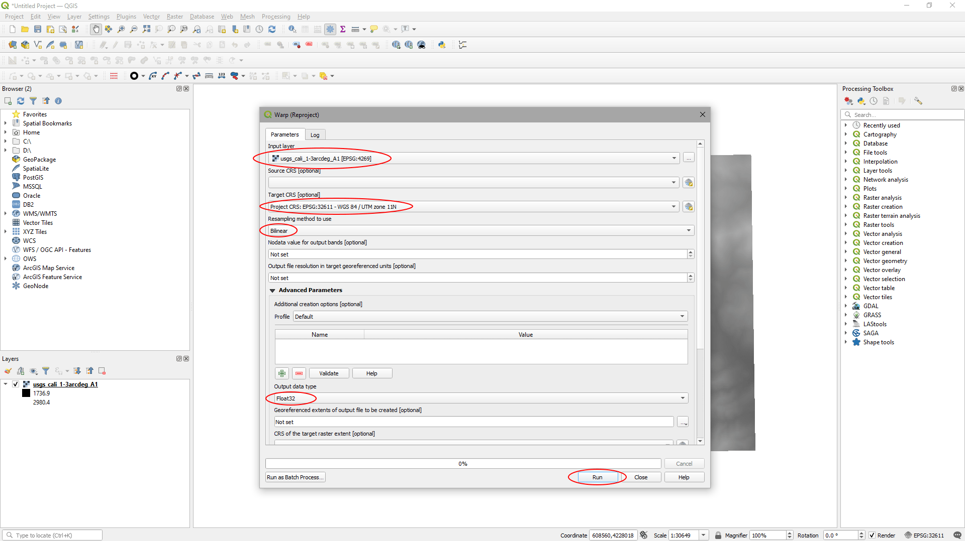
In the ‘Warp (Re-project)’ window:
- Set ‘Input layer’ to your DTM data.
- Set ‘Target CRS’ to the coordinate reference system for the project (WGS 84 / UTM zone 11N).
- Set ‘Resampling method to use’ to ‘Bilinear’.
- Set ‘Output data type’ to ‘Float32’.
- Click ‘Run’.
The ‘Re-projected’ DTM data will appear in the ‘Layers’ panel.
Step 5
Clip the DTM data to the area of interest:
Now the DTM’s in the correct CRS, we need to clip it to the area we want to use to create our landscape in UE4. Even if we wanted to use the whole DTM we would still need to clip it back to a rectangular area, otherwise we would have areas of ‘no-data’ at the edges of our DTM, which UE4 really doesn’t like.
The easiest method for this is to clip it to a box that we can draw:
- Click ‘Raster’ > ‘Extraction’ > ‘Clip Raster by Extent…’
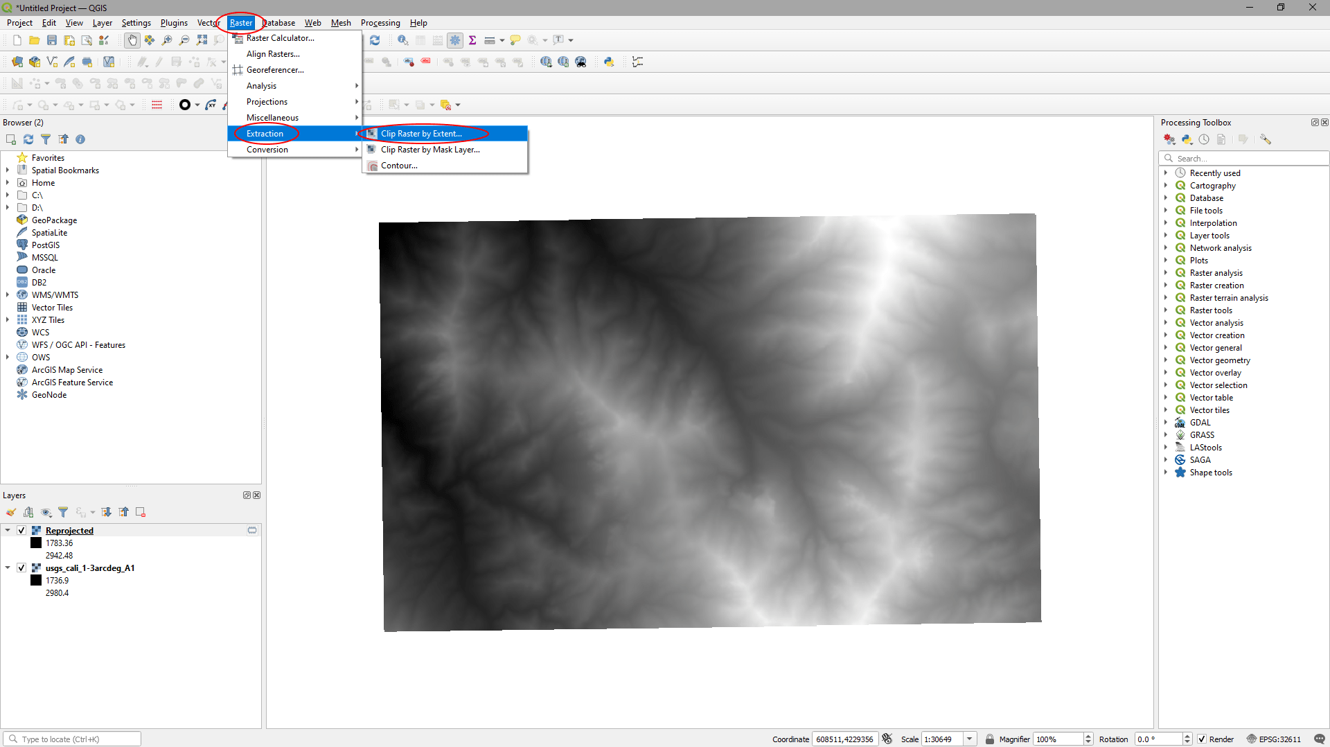
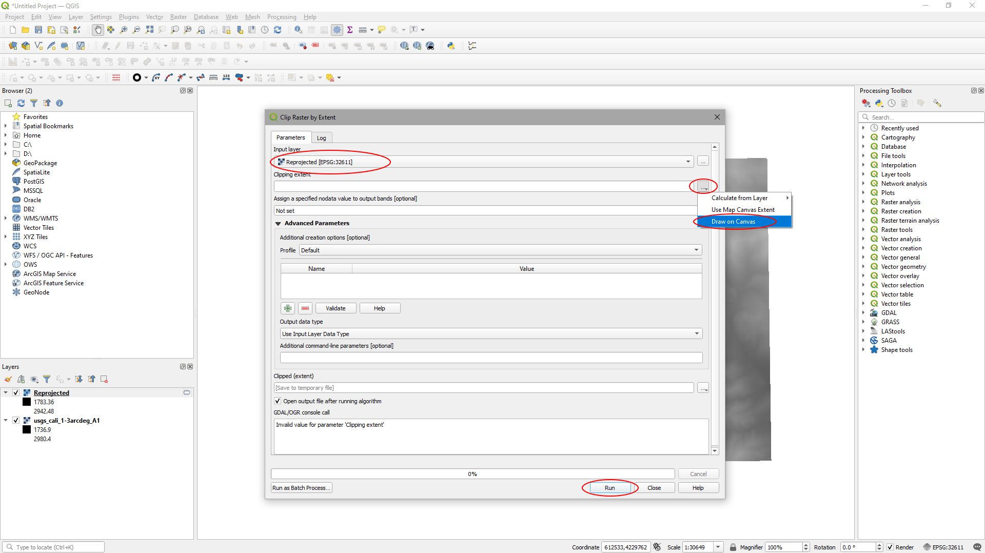
In the ‘Clip Raster by Extent’ window:
- Select the ‘Reprojected’ layer as the ‘Input layer’.
- In ‘Clipping extent’ click the button to the right of the input and select ‘Draw on Canvas’.
- Draw a box to select your area of interest.
- Click ‘Run’ to clip the data.
A ‘Clipped (extent)’ temporary file will be created and will appear in the ‘Layers’ panel.
Step 6
Export the DTM data:
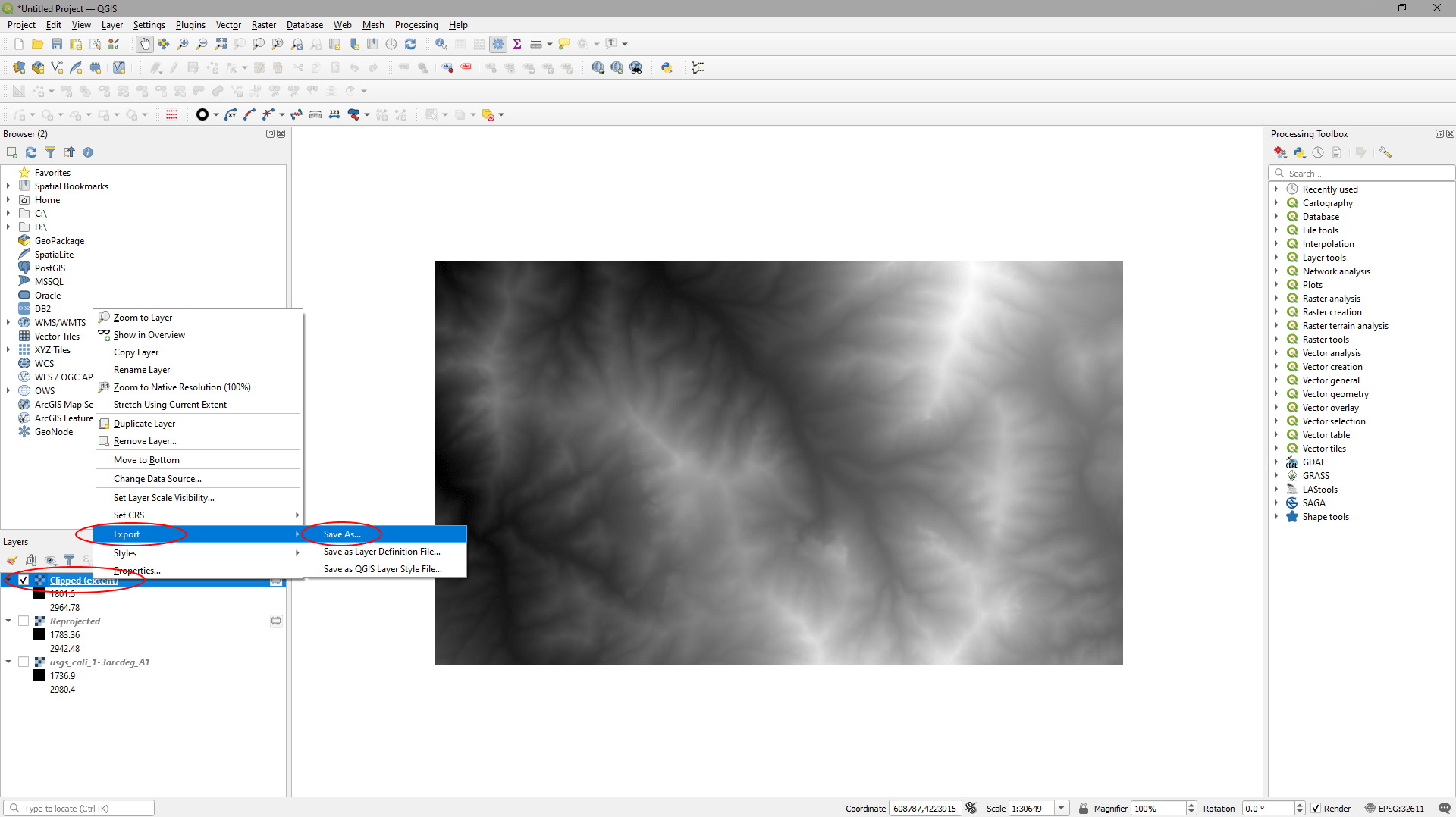
You can turn off all the layers except the new ‘Clipped (extent)’ layer to check it looks correct – it should be rectangular and the same dimensions as the box you drew in the previous step.
- Right click on it in the ‘Layers’ panel.
- Click ‘Export’ > ‘Save As…’.
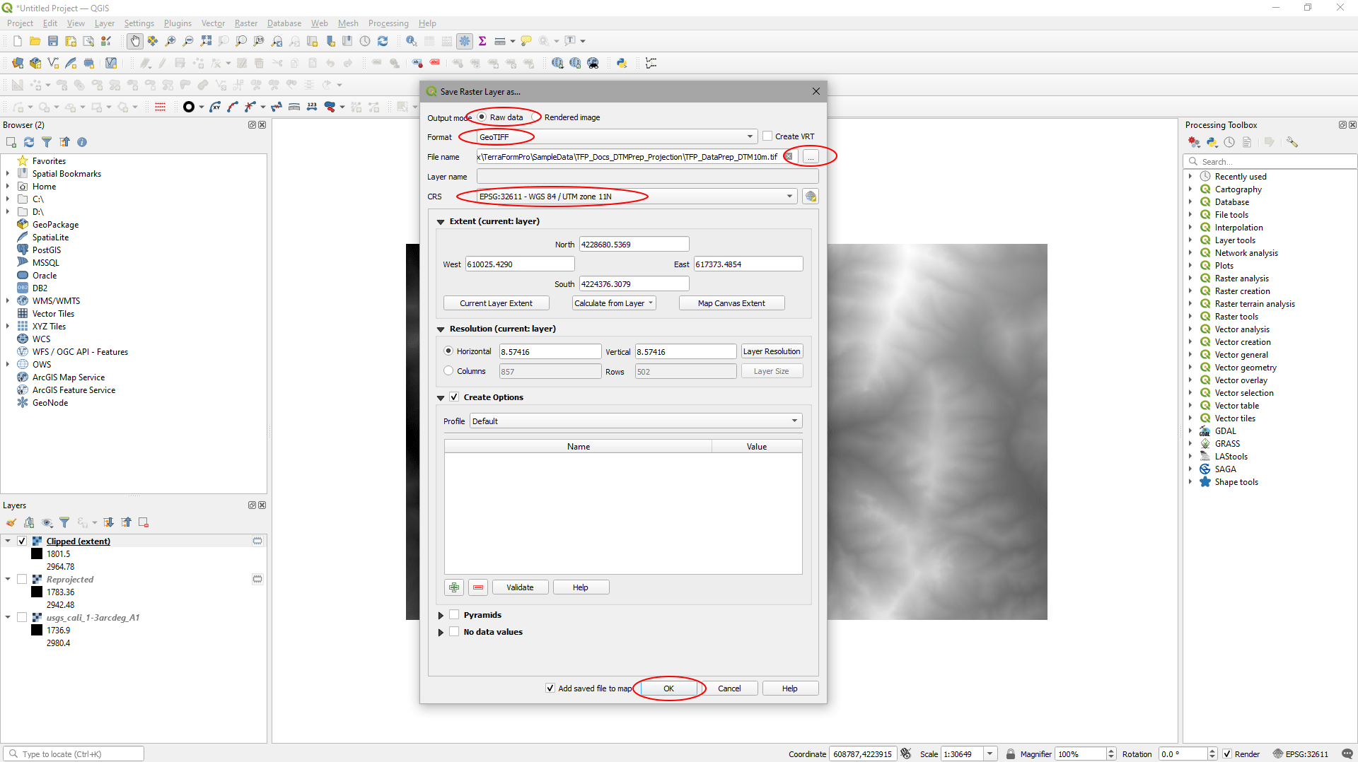
In the ‘Save Raster Layer as…’ window:
- Set ‘Output mode’ to ‘Raw data’
- Set the ‘Format’ to GeotTIFF’
- Click on the button to the right of ‘File name’, browse to a location to save your DTM file and give it a name.
- Make sure ‘CRS’ is set to ‘WGS 84 / UTM zone 11N’.
- Click ‘OK’.
Your 32-Bit Floating Point GeoTIFF in UTM projection will be exported to the location you specified.
You should now be able to import your DTM data into UE4 using TerraForm. Here’s what the data in our example looks like.
