How Can We Help?
Segment Length
For those line features that you’re intending to apply a spline mesh to, you’ll need to consider the distance between the points of your vector lines (segment length). If they’re too close together, your landscape spline segment meshes will be squashed.
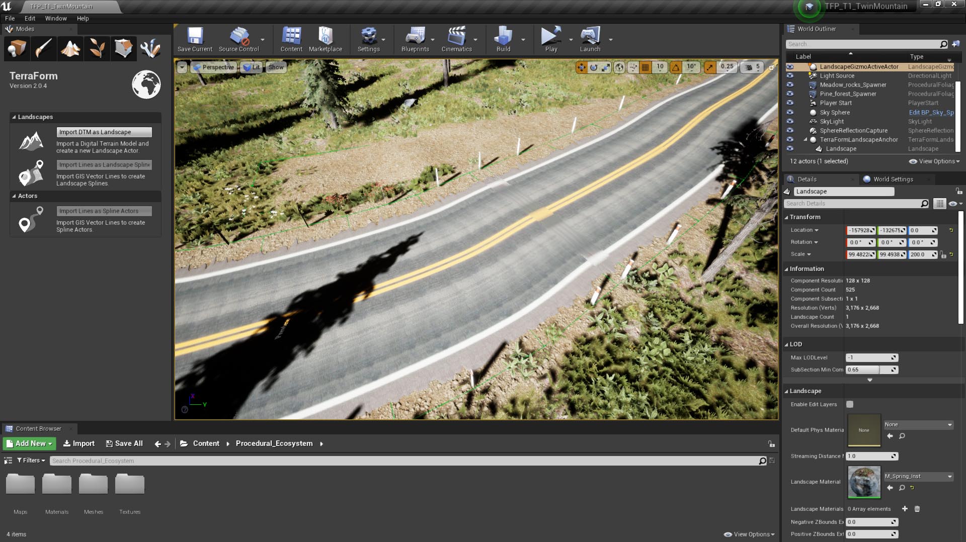
Conversely, if you’re planning to get TerraForm to snap your landscape splines to the landscape’s terrain and they’re too far apart, they won’t blend well with the terrain.
CHANGING POINT SPACING
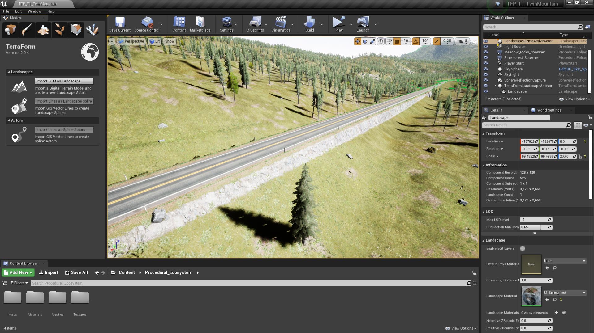
To make sure we get some nice landscape splines in UE4, we need to set the segment lengths to be slightly longer than the spline meshes we want to apply (we find 1.5x works well). This will fix both issues mentioned above, because our segment lengths will be greater than the length of the spline meshes we want to use (no squashing), and will fill long distances between spline points (ensuring a good blend with the landscape’s terrain).
Step 1
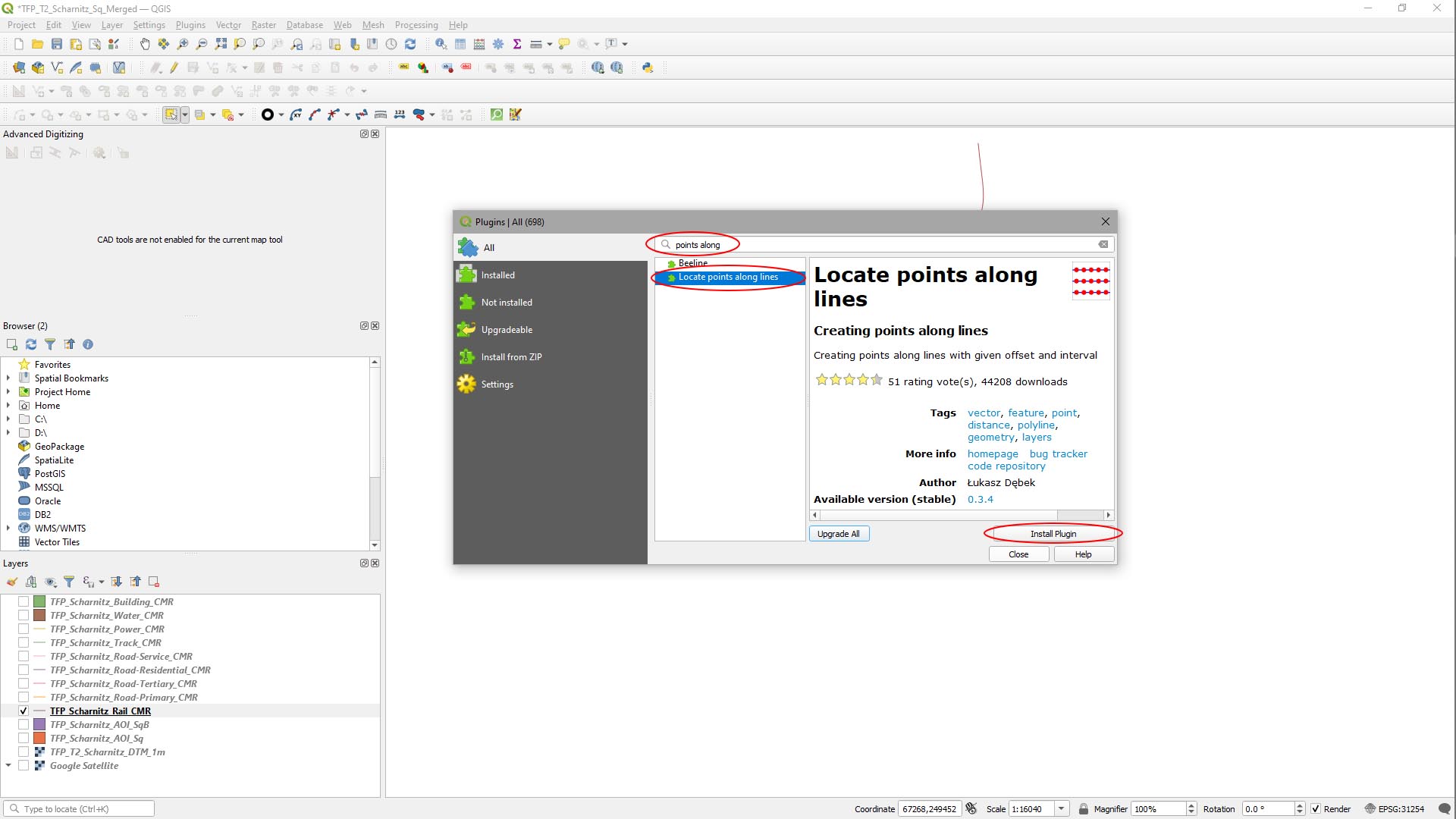
Open the Plugin – Create Points Along Lines
- There’s a really useful plugin for QGIS to help redistribute the points along lines – it’s called Locate Points Along Lines. To add this: on the main menu, click Plugins > Manage & Install Plugins.
- In the Plugins window, search for points along
- In the results, select Locate Points Along Lines, then click Install Plugin.
Step 2
Create New Points Along Lines
- Click the new Locate Points Along Lines button on the toolbar.
In the Locate Points Along Lines window:
- Set Input Polyline Layer to your rail layer.
- In the Output Layer Name field, type a name for your new layer.
- Set Interval to 22.500000 (our rail spline segment mesh is 15m long: 1.5 x 15m = 25m).
- Check Keep Attributes (If you want to keep them).
- Check Add Endpoints to make sure you retain the entire lines.
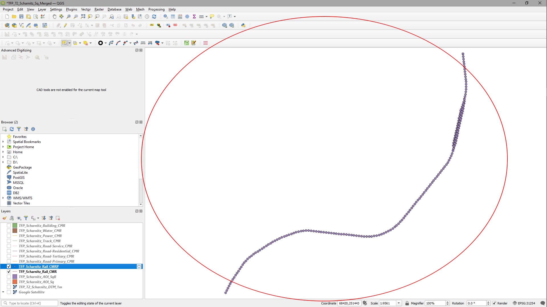
- Click Run.
Here’s what it looks like in our project:
Step 3
We now have points every 22.5m along our lines, but we now need to create lines from the points.
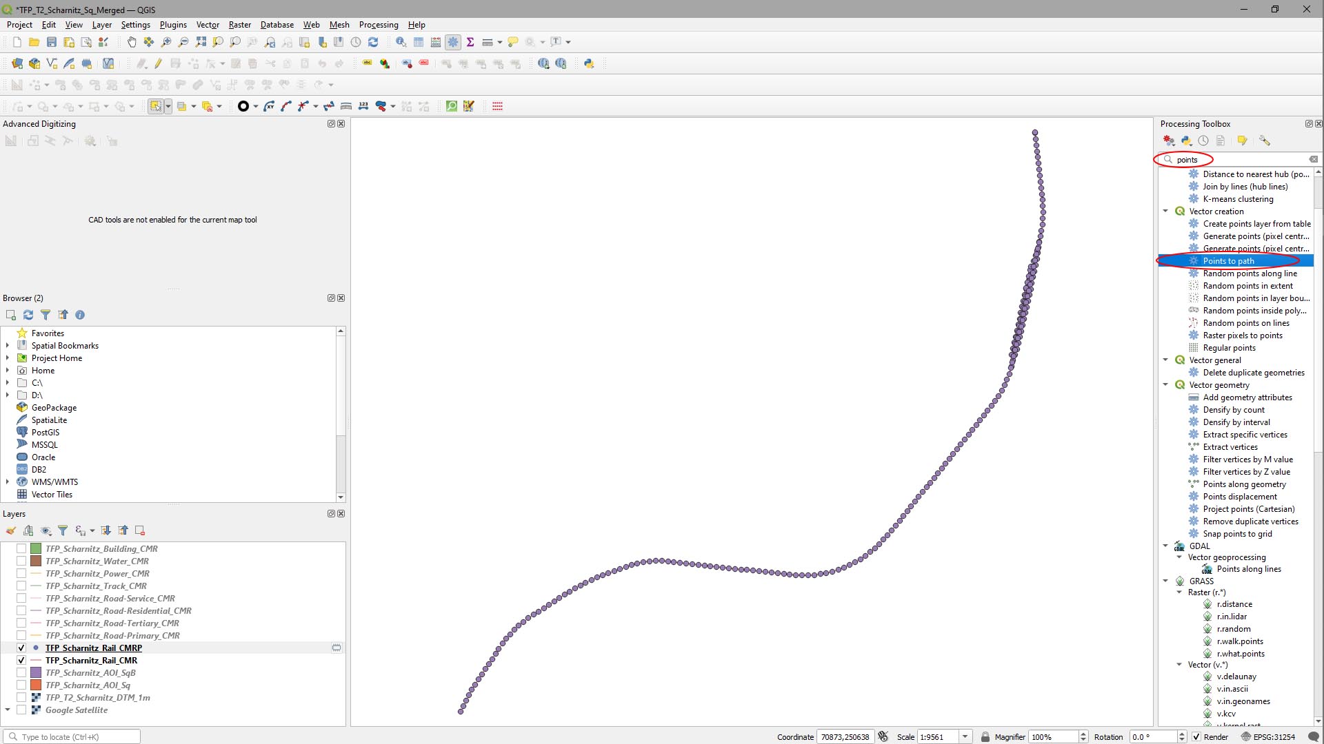
- On the main menu, select Processing > Toolbox.
- In the Processing Toolbox search field, type Points and select Points to Path.
- Double-click it to open the tool.
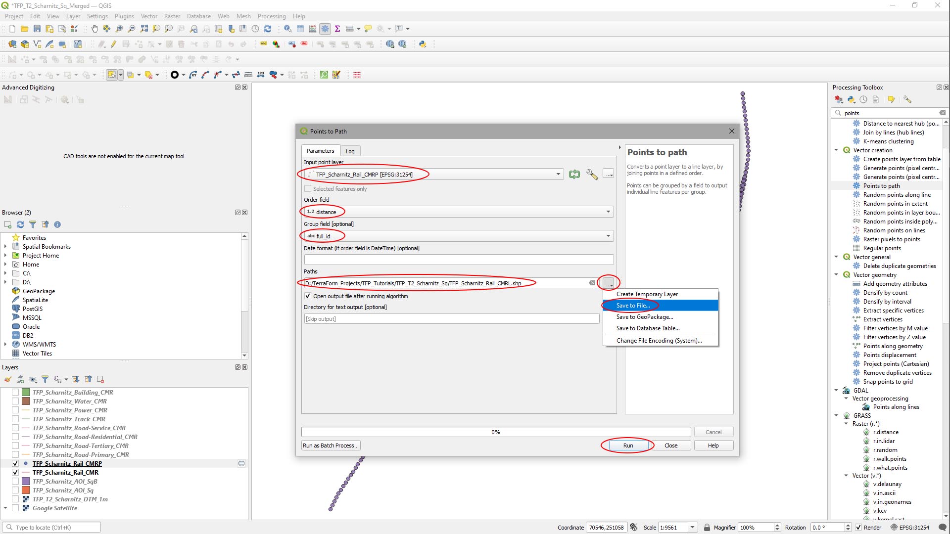
In the Points to Path window that appears:
- Set Input Point Layer to the rail points layer.
- Set Order Field to Distance (this was created by the Locate Points Along Lines tool.
- Set Group Field to Full_ID.
- Click the … button to the right of the Paths and select Save to File…, navigate to your source data folder and give the file a name.
- Click Run.
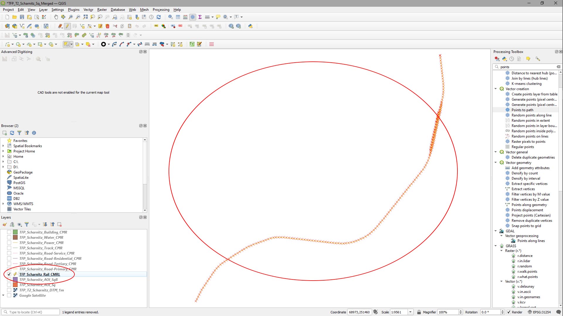
A layer is created for the new rail lines with 22.5m segments.
Clicking on the new layer and clicking the Toggle Editing button, then the Select Features by Area or Click button, we can see the new lines look good, so we can close the original rail layer and the rail points layer.
Step 4
- Depending on your source data, you may wish to repeat the Steps 2 and 3 for the other vector lines you want to apply spline meshes to.
In our case this is just the roads – the other lines we’re just going to use to modify the landscape’s material layers, then use blueprints to create content with them. However, looking at the roads, it appears the line segments are actually well spaced as they are, so we’re not going to modify them in this instance.
IMPORTANT
It’s important to remember that adjusting the spacing between points has the effect of moving where the points are, which inevitably leads to differences in the vector data set’s accuracy. You should only modify the point spacing where you can be confident you’re not otherwise affecting the accuracy of the source data, or where the source data’s accuracy is less important.
The alternative to modifying the spacing it to use shorter spline segment meshes, then randomly selecting them from an array to provide appropriate variety to avoid obvious duplication – we’ll go over than in another tutorial.