How Can We Help?
Rivers: Source Data
Rivers are a key feature of most landscapes. To use GIS data to create rivers in UE4 we need to use two processes:
- The first is to cut a channel into the landscape.
- The second is to add flowing river water.
IMPORTANT
Since DTM data is remotely sensed (using satellites or aircraft) and the sensors don’t penetrate water, the bathymetry (depth) of the river isn’t included in the DTM data. As a result, we need to create a channel for the river that’s blended into the terrain. For the purposes of this tutorial, we’re going to assume the depth of the river is constant at its centreline.
SOURCE DATA TYPES
GIS data stores rivers as either lines (centreline), or polygons (the area covered by the river). Since GIS lines can only have a single attribute value for each feature (e.g. width of the river), using lines to create rivers means that our channel will have a constant width all the way along it, which isn’t very realistic. Fortunately, with TerraForm, we can import points to create landscape splines, so we can have different attribute values at each control point (like the width).
We then have to overcome the issue that GIS data for rivers doesn’t exist as series of centreline points with an attribute for the width at each one. This tutorial shows you how to use QGIS to create exactly that from river polygons.
CREATING A CENTRELINE FROM A POLYGON
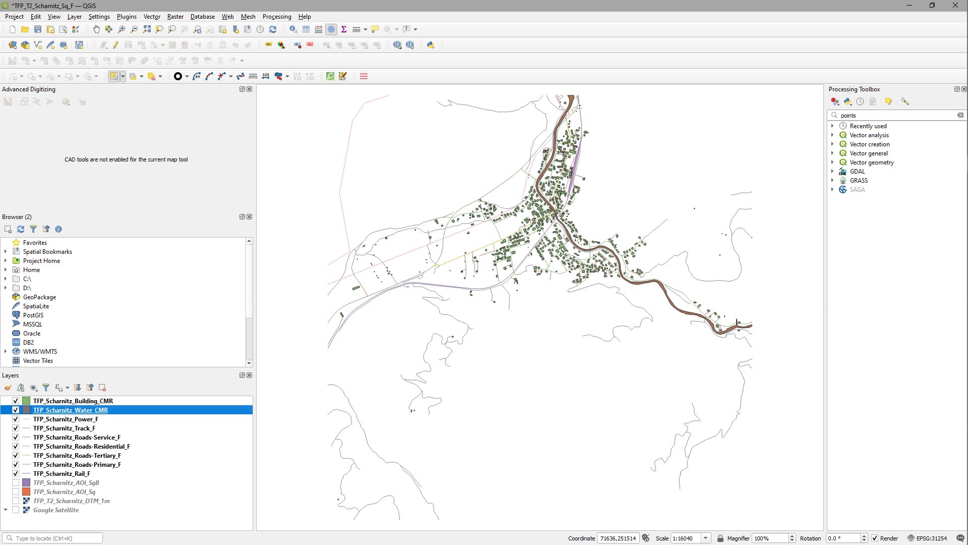
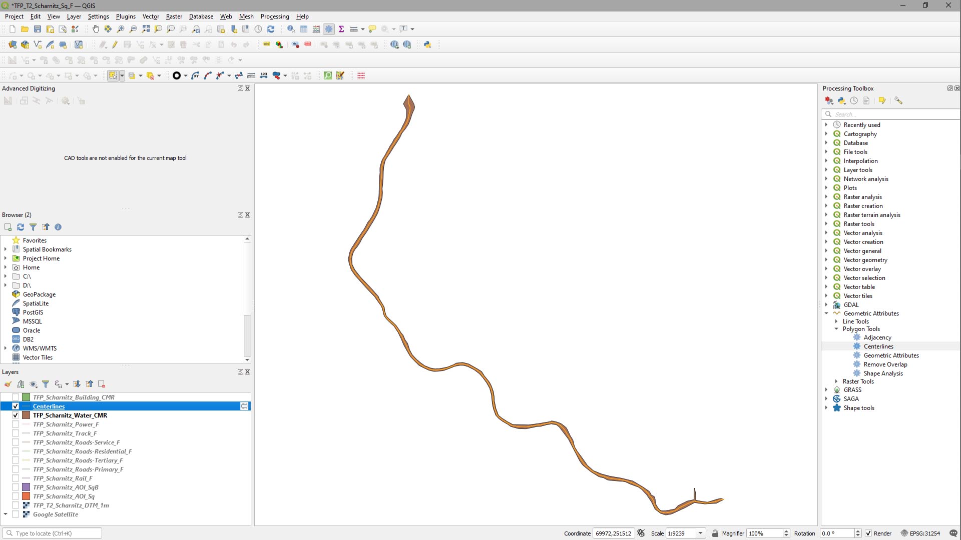
The data we downloaded using the Quick OSM plugin for QGIS included a Natural: Water (polygons) layer, which is what we’ll use as a starting point (you can follow on from that guide to see how we created this source data set).
Step 1
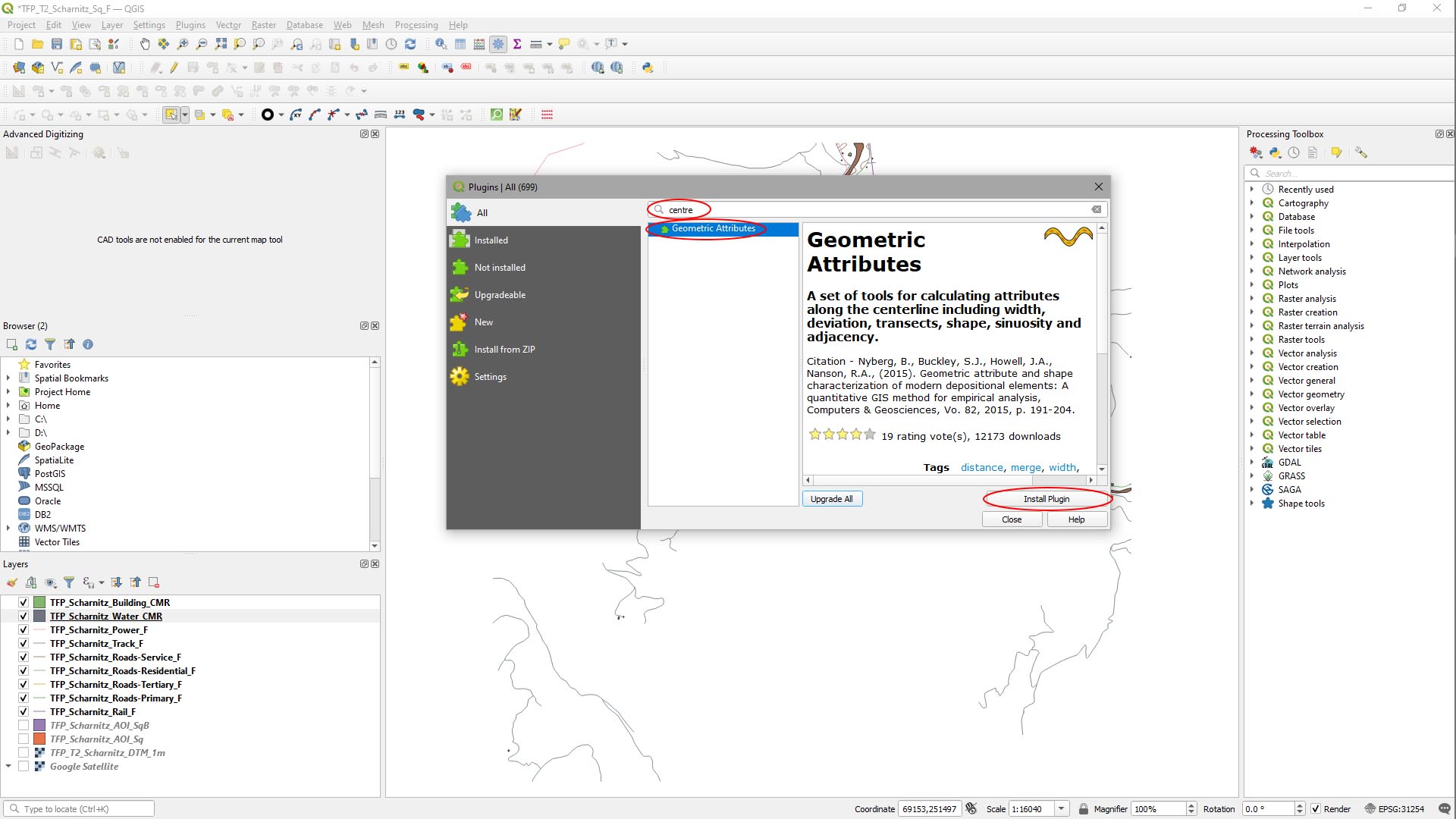
Add the Geometric Attributes plugin to QGIS.
Calculating centrelines from polygons can be quite tricky. To make things simple, we’re going to use a plugin that does most of the heavy lifting.
- On the main menu in QGIS, select Plugins > Manage and Install Plugins….
In the Plugins window:
- Type Centre into the Search Box.
- Select Geometric Attributes from the Results pane.
- Click Install Plugin.
Step 2
Edit the river polygon data.
To make it easy for the Geometric Attributes plugin to figure out the start and end of our river, we’re going to modify the river polygon by making the ends pointy.
- First close all but the water polygon layer in the Layers panel.
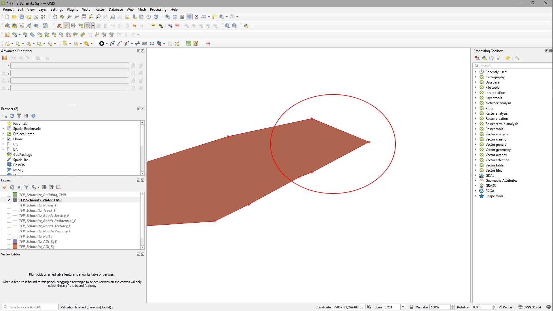
- With the water layer selected, zoom in to the end of the river polygon (we clipped it to our AOI previously), and click the Toggle Editing button, then the Vertex Tool button.
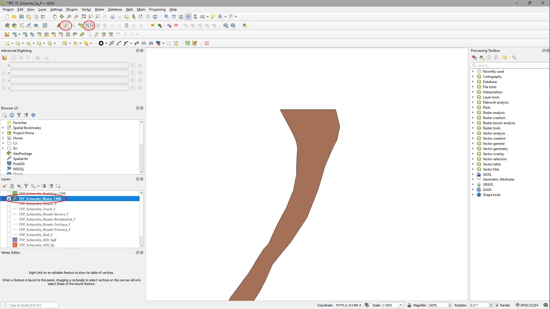
Hovering the mouse over the flattened end of our river, a midpoint vertex appears.
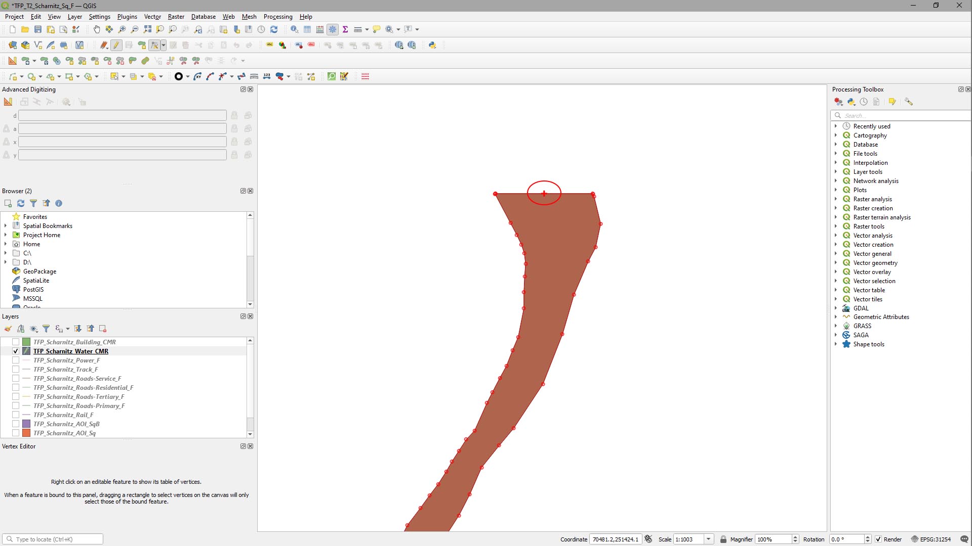
[Left-Click] it once and drag it out into a point. Then [Left-Click] again to create a new vertex.
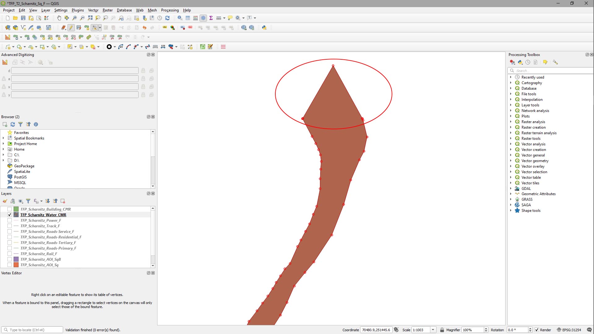
Repeat this at the other end of the river.
Step 3
Create the river centreline.
In the Processing Toolbox, select Geometric Attributes > Polygon Tools > Centrelines and in the window that appears:
- Set Polygons to the water layer.
- Set Densify Vertex Spacing to 1.000000.
- Hit Run.
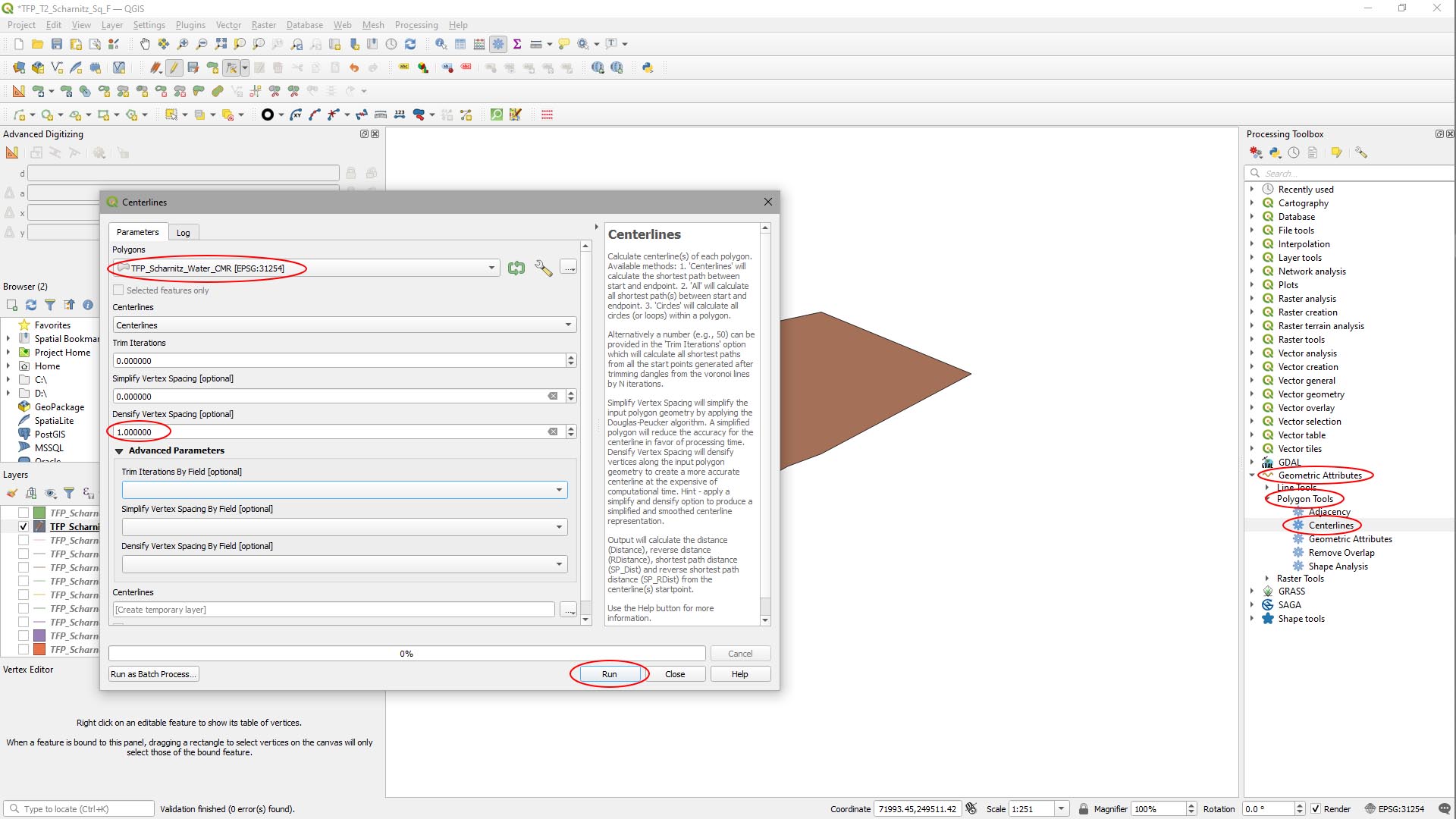
This will create a centreline down our river polygon with points every 1m.
Step 4
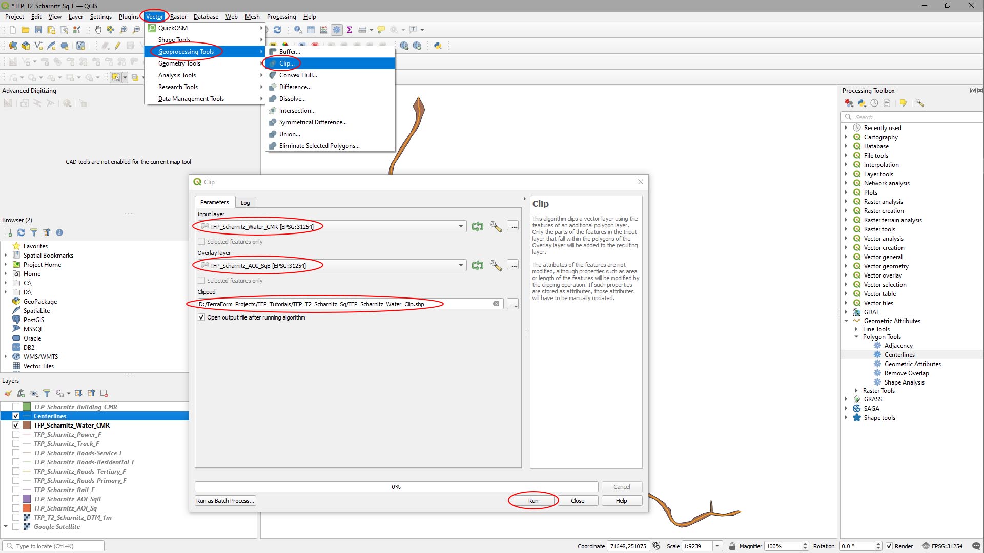
Clip the river polygon and centreline layers back to the vector layer AOI.
In the main menu, select Vectors > Geoprocessing Tools > Clip… and in the window that appears:
- Set Input Layer to the water layer.
- Set Overlay Layer to your vector AOI layer.
- Click the … button to the right of the Clipped field, navigate to your source data folder and give it a useful name.
- Hit Run.
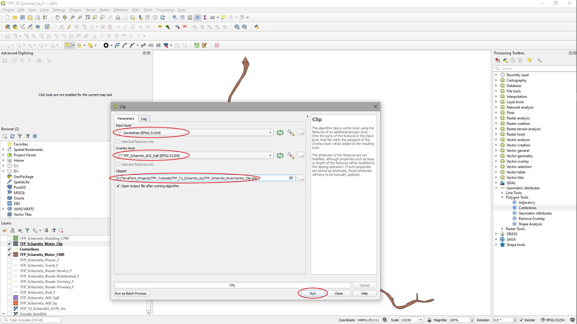
Repeat this for the Centrelines layer.
Now we can close the original polygon and centrelines layers (Layers panel).
Step 5
Use the Geometric Attributes plugin to calculate the river’s width along the centreline.
In the Processing Toolbox, select Geometric Attributes > Polygon Tools > Geometric Attributes and in the window that appears:
- Set Polygons to the clipped water layer.
- Set Centrelines to the clipped centrelines layer.
- Check the Sample By Distance option.
- Set Samples to 10.000.
- Hit Run.
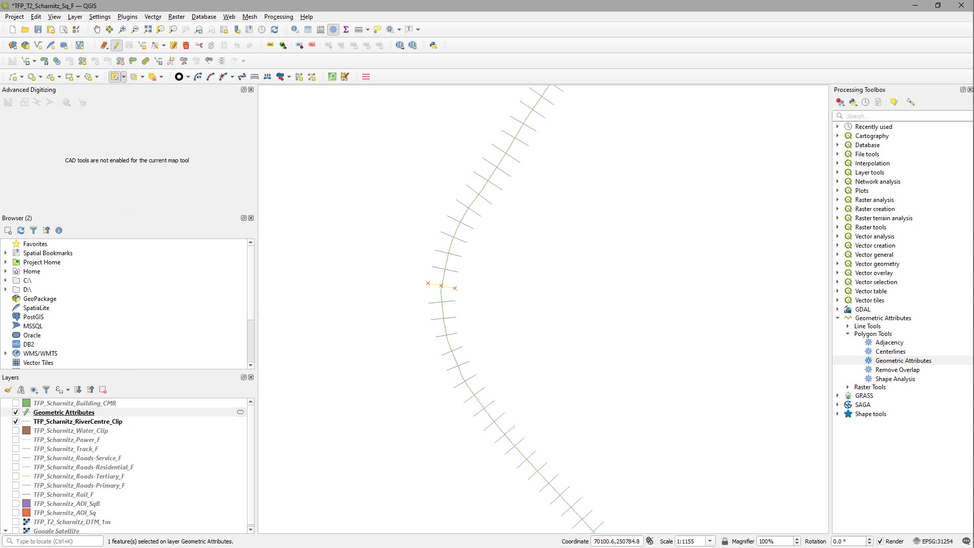
This will calculate the perpendicular distance from the centreline to the polygon every 10m.
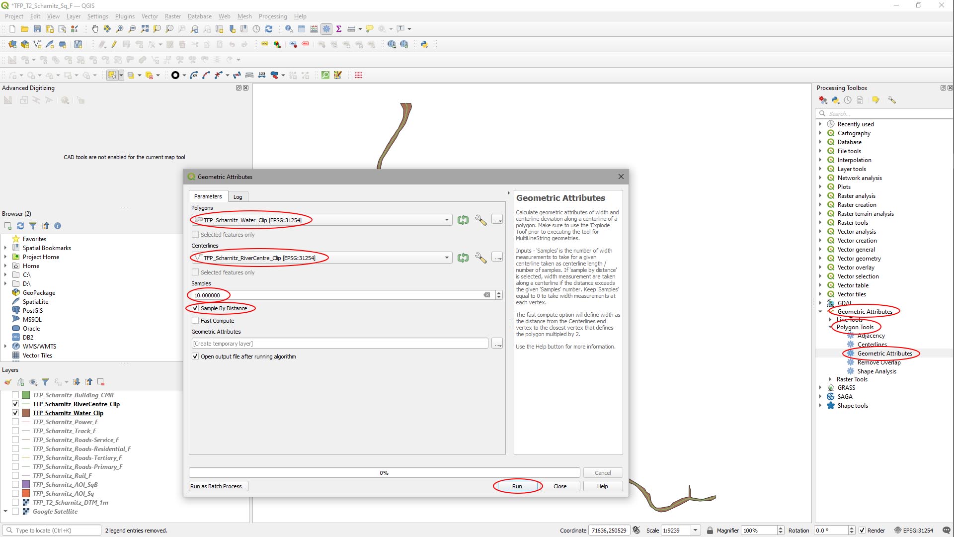
Here’s what it looks like:
Step 6
Next, we need to convert the width lines to a series of points with a width attribute.
In the attribute table for the Geometric Attributes layer ([Right-Click] Geometric Attributes in the layers panel then select Open Attribute Table, we see the width attribute values are there:
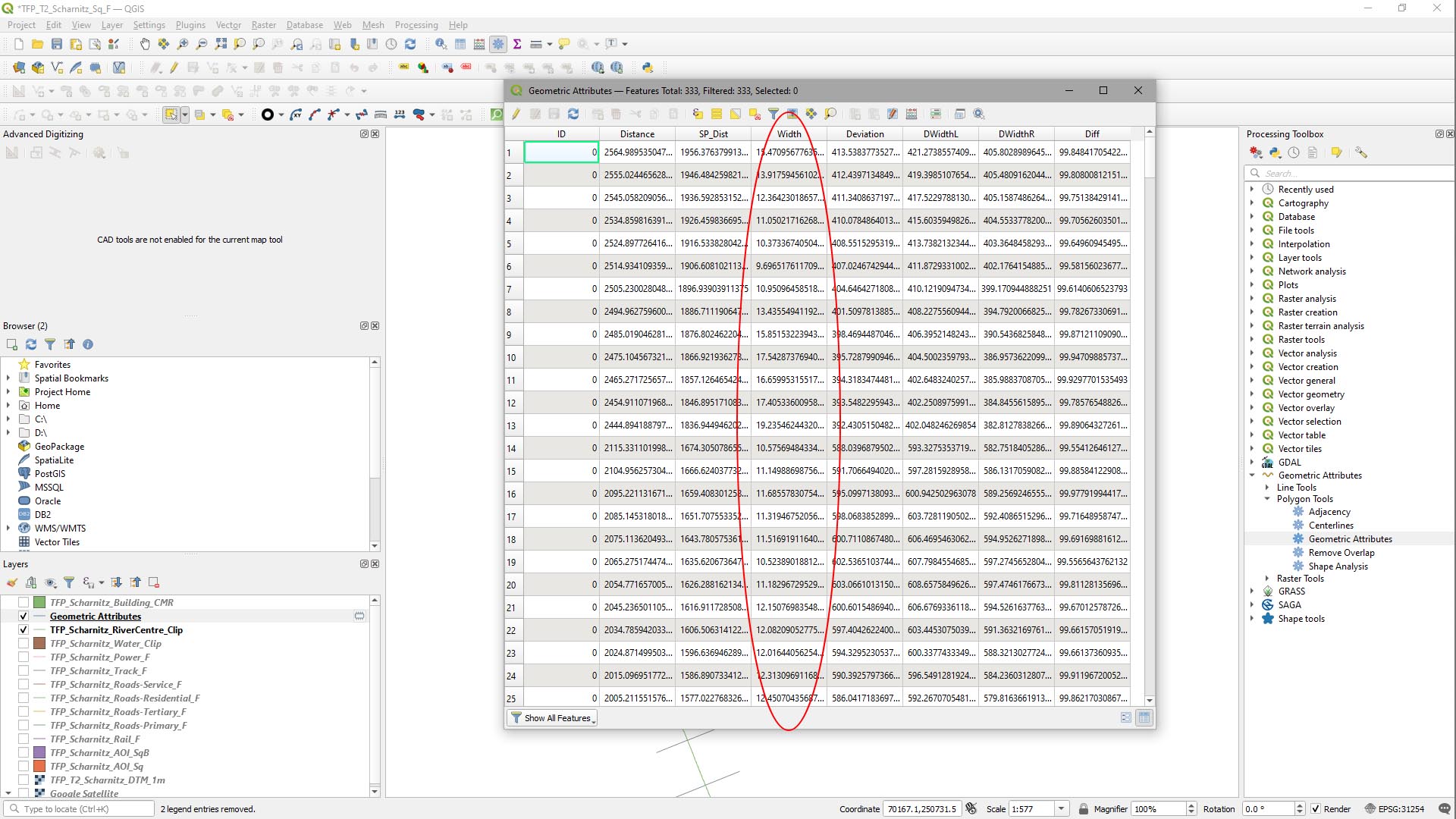
Now we need to remove the end points of each cross-section line and keep the one that’s in the middle.
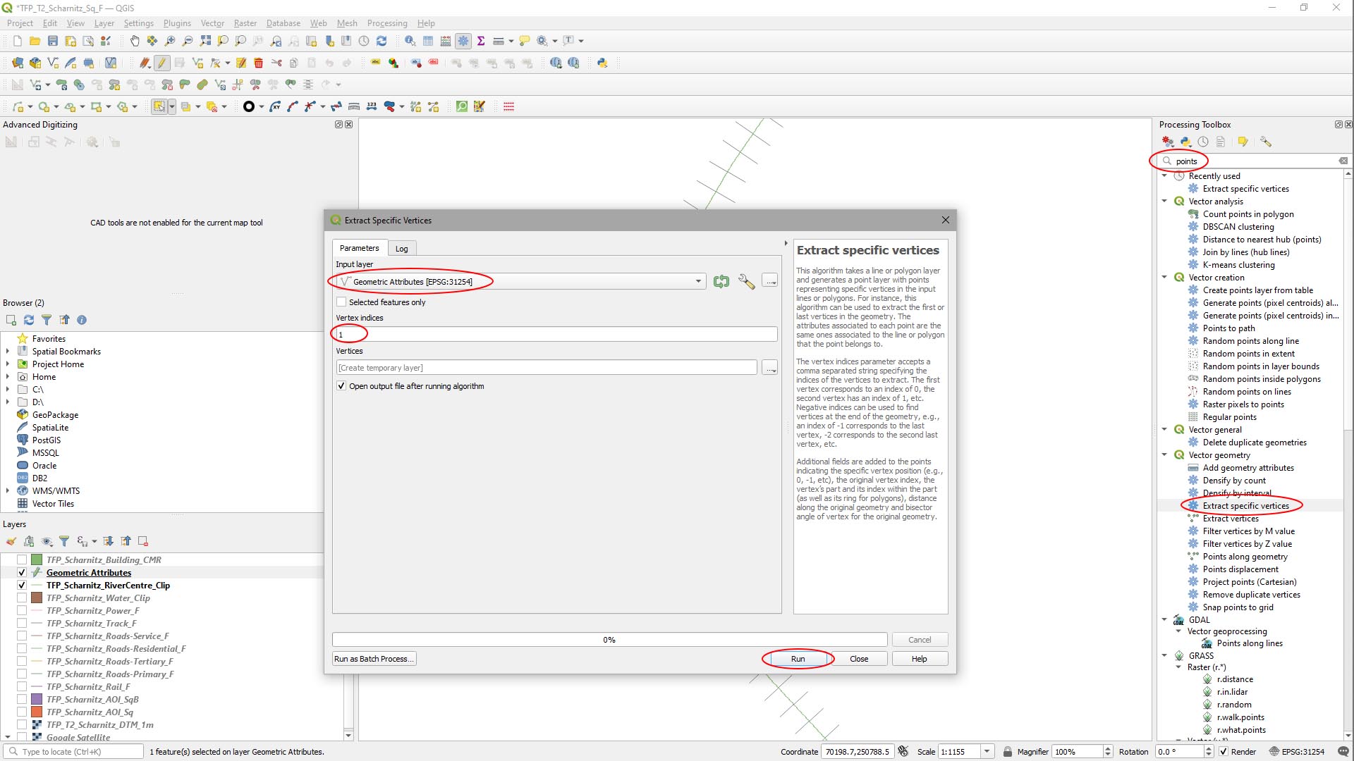
In the search box of the Processing Toolbox, type ‘points’, then [Double-Click] ‘Extract Specific Vertices’. In the window that appears:
- Set Input Layer to the Geometric Attributes layer you just created.
- Set Vertex Indices to 1 (there are 3 vertices numbered 0, 1 and 2 for each line – we want the middle one).
- Hit Run.
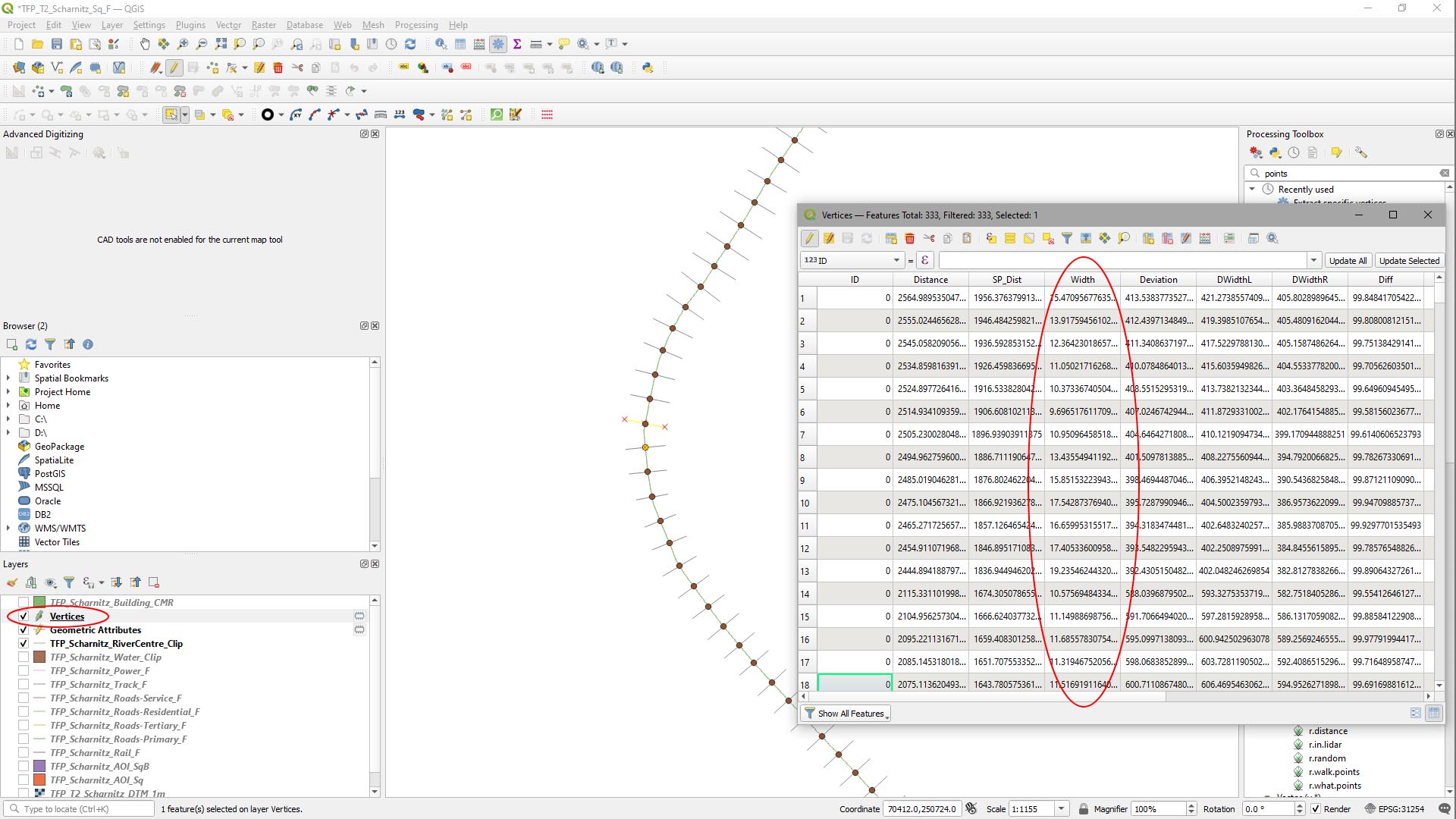
A new points layer is created with the centreline of the river and a point every 10m with an attribute for the width of the river at each point.
Step 7
UE4 (and TerraForm) want the ‘half-width’ of the river (ideally in cm), but our attribute is the full width and is in metres. To fix this, we need to add a new attribute and calculate the half-width from it.
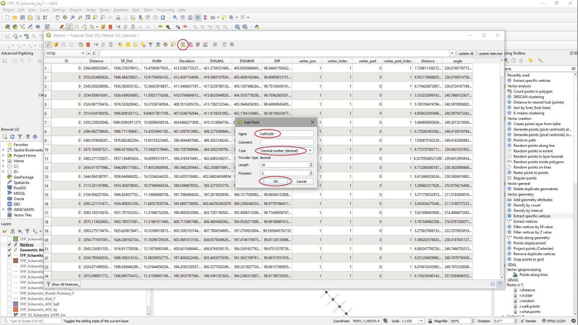
- Click the New Field button in the attributes table.
In the Add Field window, set:
- Set Name to halfwidth.
- Set Type to Decimal Number (Decimal).
- Leave Length as 10, and Precision as 3.
- Hit Run.
Now we have a new attribute field, we need to fill it with values. We have the width attribute with values in metres and we want a half width with values in centimetres.
- Set the attribute to modify to HalfWidth.
- Click the Expression button.
- In the expression editor, type ‘Width / 2 * 100‘ and hit OK.
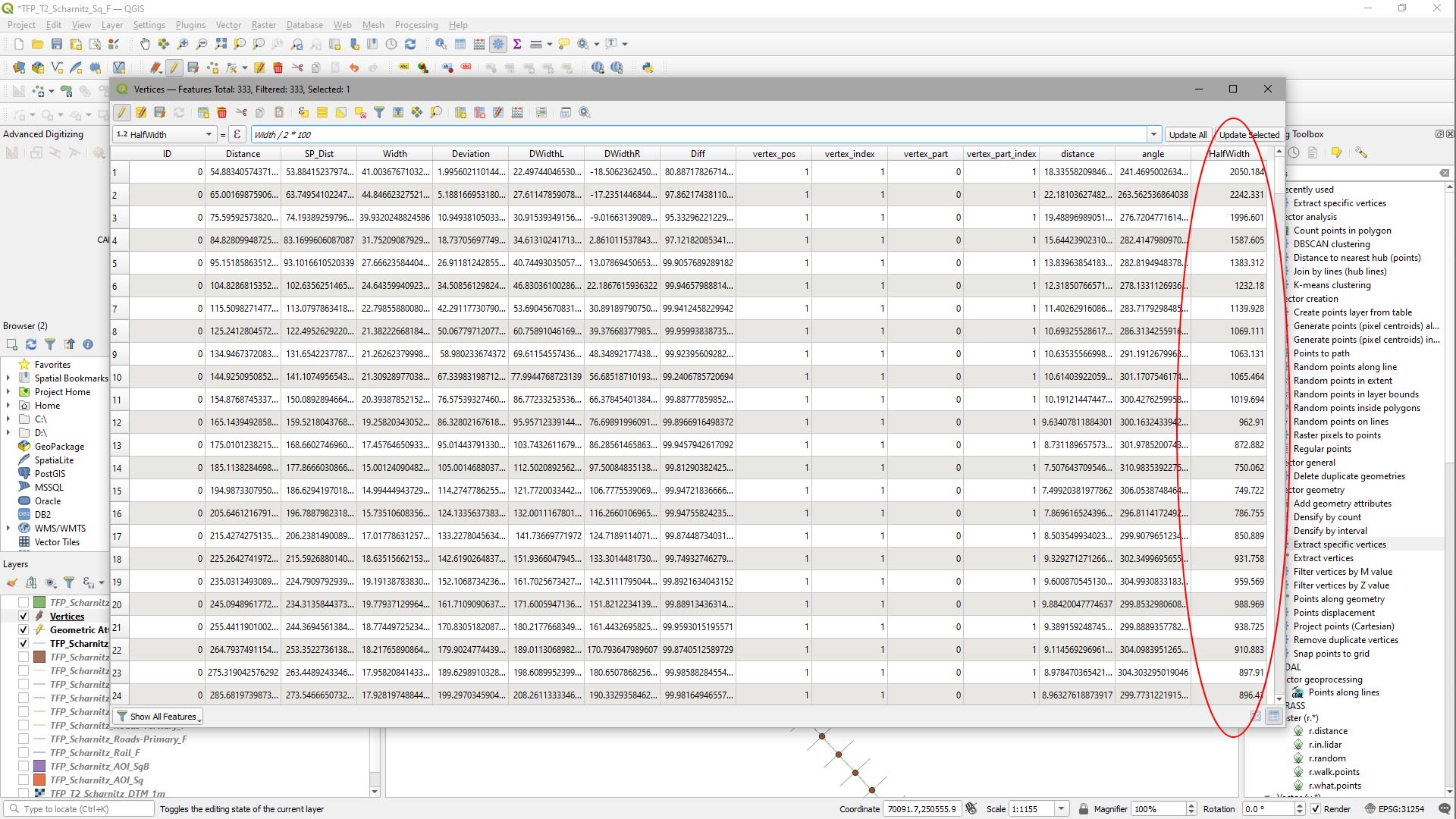
- Then in the attributes table, click Update All.
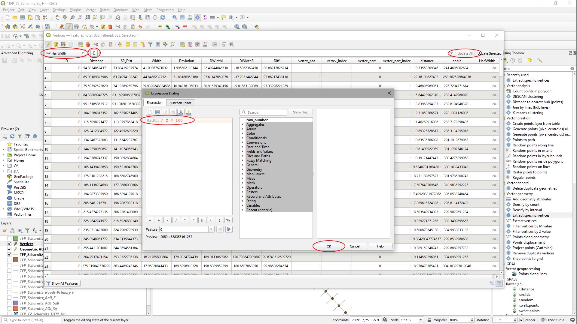
The attribute values will be populated for the Half-Width in centimetres.
Step 8
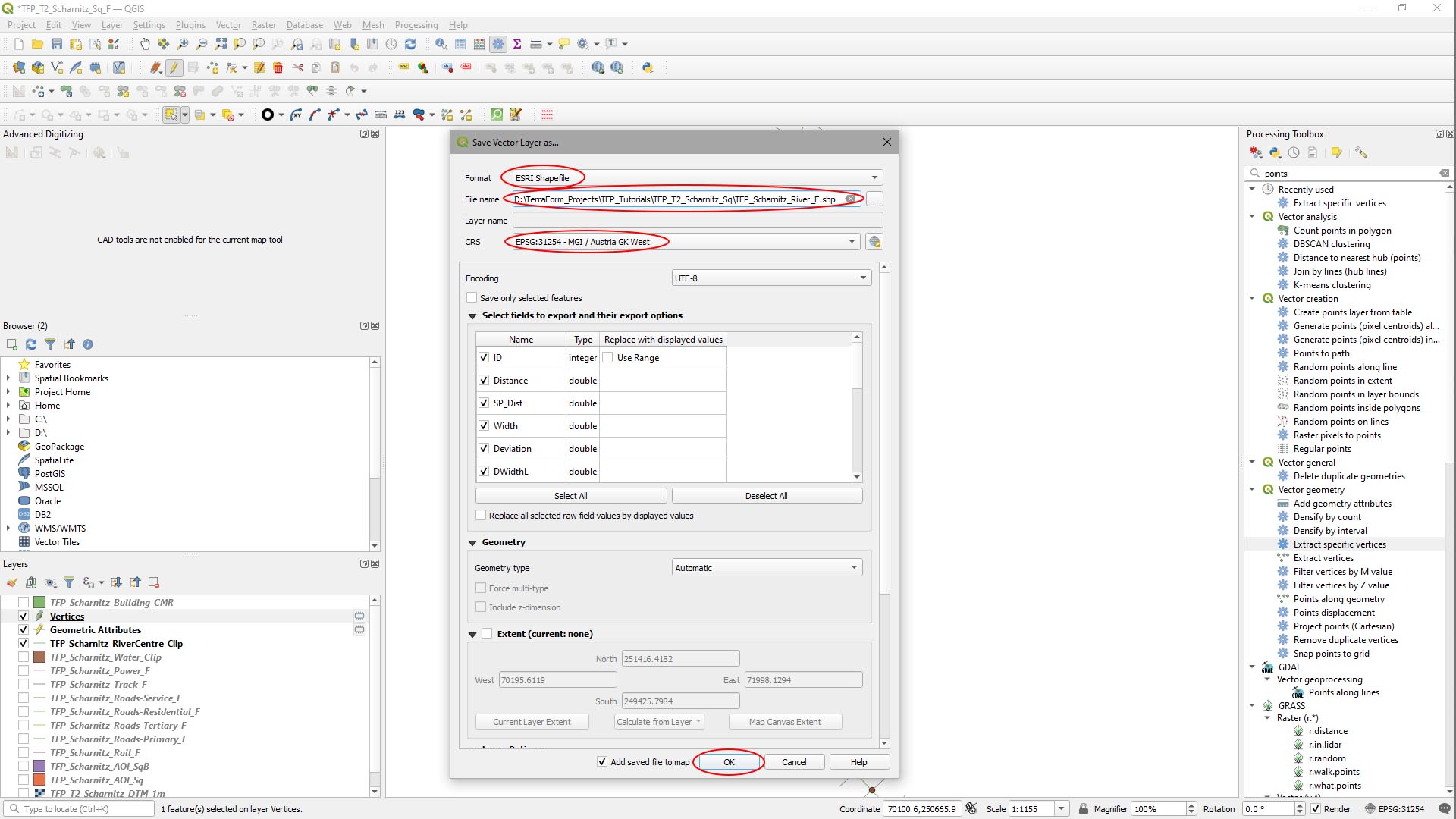
Finally, we need to export our new data to a ShapeFile we can import with TerraForm.
- [Right-Click] on the new Vertices layer in the Layers panel.
- Select Export > Save As….
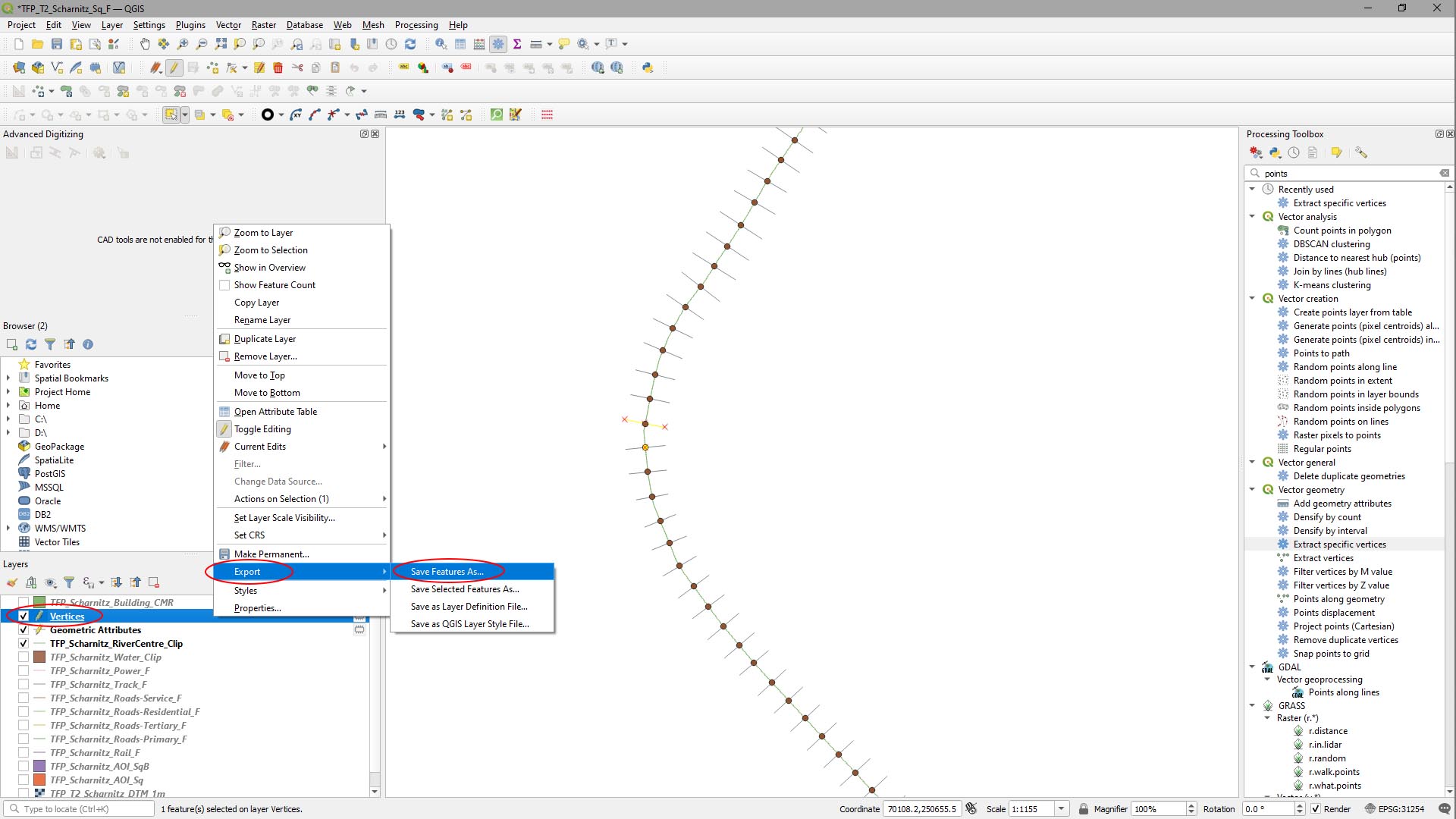
In the Save Vector Layer As… window:
- Set Format to ESRI ShapeFile.
- Click the … button to the right of File Name, navigate to your source data folder and give it a useful name.
- Set CRS to the project’s coordinate reference system.